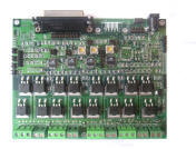
Smart Embedded Systems for    
Industrial, Commercial and Educational Applications
   Home | Products  |  Download | Ordering  | Support  |  News | Contact
  Products > Motion Control> MC433
 
PRODUCTS
HELPFUL RESOURCES
   Site Guidelines


Motion Control
MC433  4-Axis Unipolar Stepper Motor Controller 8A with G Code Processor Option
       Documents:
    MC433 Technical Manual V0.96
   MC433G Technical Manual V0.97
Description: 4-Axis Unipolar Stepper Motor controller with PWM current regulation on each channel.  PC parallel port interface with on board G Code processor option.

This product has been retired - support continues.

     
Price: MC433 $115.00
  MC433G $165.00
Click on photos to enlarge Dimensions: 3.85x3.00 in

Overview | Layout | Description | Related Products | Downloads

Overview
The MC433 is a 4-Axis Unipolar stepper motor controller that converts step/direction inputs to jumper selectable wave, full or half step 4-phase motor control.  Connecting directly to a PC's parallel port the MC433 uses ultra low on resistance Power MOSFETs (0.044ohm) capable of handling high amperage steppers with ease.  By regulating the current delivered to each phase through PWM the power needs of a particular stepper can be optimized for an intended application without the need for power sapping load resistors.  PWM initial on time, chop duty cycle and duty cycle slew rate are changed using on board potentiometers.  The PWM signal delivered to each axis is controlled by a dedicated 8bit RISC processor (ATmega168) that can be field upgraded with new control algorithms using a programming adapter.  An I2C TWI communications port allows an external TWI controller to communicate with each motor controller setting step mode, step, PWM parameters and turn off conditions on an individual motor basis.  Safety features include automatic duty cycle reduction during idle periods, motor shut off after 20 seconds,  and duty cycle slew rate adjustment for slow step rates.  The MC433 is available with an optional onboard G Code processor.  Additional accessories include several relay daughter cards, joystick input, 4-axis large LED display and a high performance G Code processor for dedicated ultra high speed half step applications.  The onboard G Code processor allows OEM's to develop their own custom control algorithms and monitoring systems without relying on a attached PC.

Features
    o  Unipolar Stepper Motor Controller
    o  8A continuous, 33A Peak (requires optional CK10 Heat Sink Kit)
    o  4-Axis X, Y, Z and A
    o  Wave, Half and Full (High Torque) step
    o  PWM variable on time, chop duty cycle and duty cycle slew rate
    o  Limit switch detection on each axis - routed to Parallel Port
    o  Stepper motor input voltage 7-35VDC
    o  Noise reduction snubber on each input
    o  4 Open NPN outputs from Parallel Port
    o  PC Parallel Port Interface
    o  Logic power supply 8-15VDC
    o  Relay daughter card interface
    o  I2C TWI Communications Port
    o  ISP Programming Port
    o  Small form factor (3.85x3.00in)
    o  Optional features:
              o  On Board G Code Processor
              o  RS-232/RS-485 Serial Interface
              o  Software controlled step mode selection
              o  Joystick interface
              o  3 Analog input channels

Component Layout

Description
The MC433 is a 4-Axis unipolar stepper motor controller that converts step/direction inputs to jumper selectable wave, full or half step 4-phase power control.  Each of the four phase coils of a unipolar stepper motor is connected to an IRF540NS Power MOSFET switch.  The IRF540 is capable of 8A continuous current load with the ability to peak at 33A.  Each phase is pulse width modulated (PWM) to allow operation over a 7 to 35 volt range.  PWM adjusts average current delivered to the stepper motor to better match the resistance/inductance of the motor without the need for load resistors.  This ensures maximum power is delivered to the motor over a range of load conditions and motor types.  PWM parameters are adjusted using three potentiometers - initial on time, chop rate duty cycle and duty cycle slew rate verse step rate.  Chop rate is fixed at 12KHz.   On time is the amount of time a switch remains on before PWM operation takes over – this allows the current to build to a maximum level as quickly as possible.  Duty cycle is the percentage of on-time to off-time at a given chop frequency.  Duty cycle is used to set the average current delivered to the motor.  Duty cycle slew rate adjusts the duty cycle based on the duration of a step.  As the step rate slows down (motor turns slower) the duty cycle is adjusted to deliver less power to the motor thereby maintaining constant current.  Each motor can be individually set for wave, full, half step mode or be disabled by setting two jumpers on a four pin header. 

A dedicated 8bit 20MHz RISC microprocessor (ATmega168) controls each axis. The microprocessor monitors step/direction inputs, limit switch input and PWM settings to generate the appropriate step sequence (wave, full or half) based on jumper settings.  Three potentiometers set PWM operation for all 4 axis.  The control processor automatically reduces current to the motor after 1.5 seconds by reducing the duty cycle and turns the motor off after 20 seconds.

The MC433 is controlled via a PC compatible DB25 parallel port interface connector. The Parallel port interface has four Step/Direction inputs, four auxiliary outputs and four limit switch inputs. The four auxiliary outputs are connected to a Relay Adapter connector and an open NPN control connector.   Limit switch inputs are connected to four  0.1” pin headers  with pull up resistors  -  pulling the limit switch input to ground deactivates a stepper motor. 

An I2C TWI communications port allows an external TWI controller to communicate with each motor control processor individually to set step mode, activate a  step, PWM parameters, limit switch handling and turn off conditions. 

The MC433 has a 24pin header connector (J18) for attaching an optional G Code control processor.  The optional high performance G Code processor supports USB 2.0 protocol.

Software Tools
The MC433 is designed to work with a variety of third party G Code software programs.  
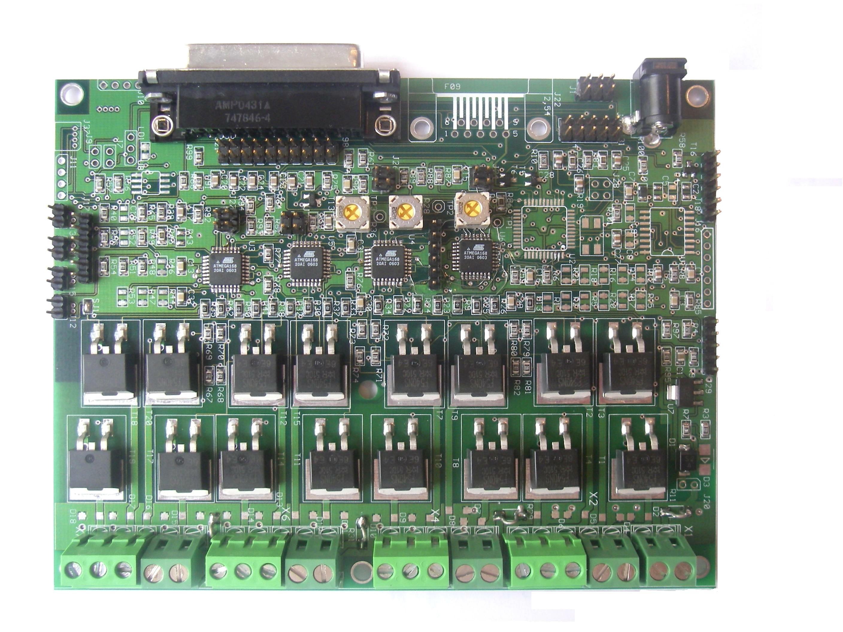
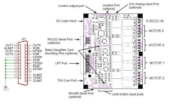
Step input for each axis requires an active high pulse lasting at least 2useconds – step inputs are edge triggered.  A high level on the Direction input will turn the stepper clockwise or counterclockwise depending on how the motor is connected to the drive port.  The direction signal is sampled after the step trigger so it must remain stable for at least 10useconds after the step trigger.

Control Processor Reprogramming
The Software in each Motor Control Processor can be user upgraded the next software release using a free desktop programming utility MC433Prog.exe.  MC433Prog.exe can be downloaded from the download tab.

Expansion Options
The MC433 has several expansion options:  Relay Adapters, Joysticks, DRO and USB Communication Controllers. 

Three Relay adapters are available - each controlled by the Auxiliary output lines. A low current DC relay array capable of handling 24VDC at 2A or 120VAC at 0.4A ,  a high current relay array capable of handling  30VDC at 4A or 120VAC at 2A and a hybrid MOSFET controller that can be configured to control three small stepper motors or operate as 12 independent 2A 30V switches.

Related Products
The following products can be used with the MC433 and MC433G.

    MC433 and MC433G Options

       CK10          Cooling Kit for MOSFETs
       MC5            Four Channel Relay Adapter        MC5 Technical Reference Manual.pdf
       SAM48G    G Code Processor Daughtercard with USB 2.0 and ARM7 Processor
       MC-USB    USB 2.0 Communications Controller

    MC433G only Options

       CJ14            Four Axis Joystick Controller    CJ14 Joystick Technical Reference Manual.pdf
       CJ34            Four Axis Smart Joystick Controller (TWI device)
       DRO4          Four Axis 4x12 LCD Display (TWI device)
       DRO84        Four Axis 8 Digit LED Display (TWI device)


Downloads/Revisions
The following technical datasheets, hardware and software downloads are available.  For information on how to download the latest Motor Controller software or G Code processor software contact support@soc-robotics.com - this code is sent via email request only.  Note - MC433 units shipped before August10th should upgrade to the latest release.  The MC433 Convert Utility is now available for download along with the new V0.99b Motor Control Software.  Note that Motor Control Software V0.99b is the latest release and contains a simple method for locking PWM characteristics on a per motor axis basis:

       Motor Controller:   V0.95      Released August 10, 2007    MC433MotorC_V0.95.zip
       G Code Processor:  V1.64      Released August 31, 2007    MC433G_GStep_V1.68.zip

       Beta Release 0.97/1.78:
           Motor Controller  - Version:     V0.97b      MC433_V0.97.zip
           G Code Processor  - Version:   V1.78      MC433G_V1.78.zip

      Beta Release 0.99b (Released April 9, 2010):
           Motor Controller  - Version:     V0.99b      MC433_V0.99b.zip

      Alpha Release 1.00/1.92 (Scheduled for the week of May 29, 2010)
           Motor Controller  - Version:     V1.00     
           G Code Processor  - Version:   V1.92     

      MC433 Rev 1.1/1.1b Technical Hardware Manual ->   MC433 Technical Manual V0.96
      MC433G Technical Hardware Manual ->   MC433G Technical Manual V0.97
      MC433 Convert Utility Manual ->   MC433 Convert Utility Manual
      CJ14 Joystick Technical Hardware Manual ->   CJ14 Joystick Technical Reference Manual
      MC5 Technical Hardware Manual ->   MC5 Technical Reference Manual
      Parallel Port Status Monitoring Utility ->   parmon.zip
      DNC Drip Feed Utility for MC433G ->   ngload.zip
      MC433 Test Utility GstepPP.exe (V0.98) -> GstepPP_V0.98.zip

       MC433 Programming Utility MC433Prog.exe -> MC433Prog_V1.24.zip


     Motor Control Processor -> ATmega168 Processor Datasheet
     On Board G Code Processor -> ATmega644 Processor Datasheet

Home | Products  |  Download  |  Support  |  OrderingNews Contact
© Copyright 2003-2009   SOC Robotics, Inc. All rights reserved.  Privacy Policy  |  Terms of Use Disclaimers
 webmaster@soc-robotics.com  Last update:  August 24, 2009